An Intuitive Guide to Maxwell’s Equations
An Intuitive and Visual Guide to Maxwell's Equations
Introduction
In 1865, James Clerk Maxwell published one of the most important papers ever produced. The paper was published in the Philosophical Transactions of the Royal Society and was called: “A dynamical theory of the electromagnetic field.” The paper might have been the most significant occurrence in the history of physical sciences, as it described the evolution of the electromagnetic field.
Why was such a description so important? Well, for one, we live in an electromagnetic world. Virtually every force we experience in everyday life (with the exception of gravity) is electromagnetic in origin. It was from Maxwell's equations that electromagnetic waves were predicted to exist. From this mathematical formulation, Maxwell determined that the speed of propagation of electromagnetic (EM) waves was the same as the speed of light, and thus showed that EM waves and visible light were really the same thing. Using the equations, we could mathematically construct and deduce the behavior of light and other electromagnetic radiation!
The importance of Maxwell’s work wasn’t obvious immediately though. For more than 20 years, his work was largely ignored by the scientific community. Why?
Well … physicists and mathematicians had a hard time understanding it. The equations in their original format amounted to 20 equations, not the 4 elegant ones we have familiarity with today. Not only that, but they were incredibly complicated and difficult to grasp. Most physicists at the time were not equipped to deal with algebraic complexity of that extent. On the other hand, mathematicians also could not grasp what they meant; Maxwell used physical language to explain them, so it was not accessible to the mathematical community at large.
These weren’t the only reasons that the theory didn’t catch on. The predominant world view at the time relied on mechanics and the universe was seen as being moved by ‘wheels and gears’ beneath the fields which Maxwell’s theory relied on.
What exactly are fields?
Well, fields can be thought of as a function acting throughout space and time. The predominant thinking at the time tried to account for such fields through mechanical structures composed of ‘wheels’ and ‘vortices’ which carried the mechanical stresses that the these fields propagated. Of course, such thinking made it difficult to grasp the beauty and meaning of the equations. Maxwell’s theory only becomes simple and elegant once we start to think of the fields (mathematical functions) as being primary and the electromagnetic stresses and mechanical forces as being a consequence of such fields, and not vice-versa.
The idea that such fields were the primary constituents of the universe did not come easily to Maxwell’s contemporaries. Fields were an abstract concept: mathematical objects which had no physical analogue. His equations were partial differential equations which weren’t accessible to simple interpretation. It wasn’t until the arrival of Oliver Heaviside, who reformulated and simplified the equations, as well as the next generation of physicists (Hertz, Lorentz, and Einstein) that the revelation came through: the universe was not built using the laws of mechanics. It was built through the laws of mathematics and the field equations.
The goal of this guide is to give an intuitive concept of what Maxwell’s equations represent, as well as capture the beauty of the physical concepts they embody.
“To see the beauty of the Maxwell theory it is necessary to move away from mechanical models and into the abstract world of fields. To see the beauty of quantum mechanics it is necessary to move away from verbal descriptions and into the abstract world of geometry. Mathematics is the language that nature speaks. The language of mathematics makes the world of Maxwell fields and the world of quantum processes equally transparent.”
- Freeman Dyson
Fields
What is a field?
A field can be thought of as a function working across space / time.
It’s important to note that the concept of a field cannot be broken down into something which has a material or mechanical analogy. Sometimes, physicists think of a field as the aggregate effect of exchange or virtual particles which are governed by a quantum field theory, or the effect of the curvature of space time, but it’s important to note that these exchange particles and geometries themselves can also be thought of as mathematical abstractions. We can try to think of a field as some sort of substance, but in reality, there is no substance and there’s no everyday intuition we can use to grasp them other than the basic intuition of having a mathematical function spread out throughout space and time. In other words: the mathematics are the interface, and they define exactly what we can expect from a field. How this interface is implemented is not defined and it’s not something that human beings have been able to figure out.
It’s easy to get hung up on the notion or question of asking ‘is a field real or not?’ We humans grow up in a world with objects. Our brains are used to breaking down the world into divisible parts and constructing it based on the notion of having ‘things’ which can be inspected by the senses and which are denoted by nouns. These ‘things’ furthermore have mass and volume, and they have discrete boundaries.
The Greeks were the originators of this conception. They imagined that ‘things’ were built out of smaller things, like atoms and molecules. When the atomic theory came about, they expected the atoms themselves to have some sort of mass, shape and size, and to be a microcosm of more things. Let’s take sand as an example. To the careless eye, sand seems like a fluid, since quantities of it appear to freely merge and split, but on closer inspection, it’s just a bunch of tiny objects which can be described as individual ‘things’ interacting with each other.
The world of quantum mechanics and quantum field theory introduce a different conception of what things are though. It turns out that elementary particles can’t be thought of as individual ‘things’ which have a volume. In fact, if particles did have a volume, physics wouldn’t work! We would end up with "surfaces" of electrons behaving in an impossible manner and spinning faster than the speed of light.
Well then, you say, what if particles aren’t objects with a volume, but points in space?
It turns out that this notion isn’t easily prone to interpretation either! No one actually knows or understands what a ‘point mass’ is! It also has a bizarre implication: if indeed we did have volume-less point masses, we obtain something with an infinite density! In theory, the entire universe could be squeezed to a single point!
So how can we deal with this? Well, it turns out that all the properties that you associate with ‘stuff’ are actually explainable in terms of electromagnetic fields and masses (which general relativity describes as a component of a tensor field). It turns out that the ‘object oriented’ definition of the universe can be better understood in terms of continuous fields governed by mathematics rather than individual objects or atoms with individual properties.
Types of Fields
There are 2 primary types of fields which we’ll discuss: scalar fields and vector fields. The reality is that we could also encounter other types of fields (such as tensor or spinor fields), but we’ll leave these out of the discussion for now to focus on the ones we’ll need to understand in order to get familiar with Maxwell’s equations.
So, what is a scalar/vector field?
Well, a scalar field takes a point in space as input and outputs a single numeric value, while a vector field outputs a vector with a magnitude and direction.
Below, we’ll show a few examples of fields and illustrate what they mean.
Temperature
Let’s imagine that we’re climbing a mountain. As you climb, you notice that the higher you climb, the colder the air gets. We also notice the general heuristic property: the air gets colder at a typical rate of about 3 or 4 degrees Celsius for every kilometer that we climb.
Now, let’s pretend that we’re observing a large terrain map and we want to ask: what’s the temperature of air at point (x, y, z)?
We can do something very difficult and attempt to create a table which maps every point in space (over the terrain) to a definite temperature, or, we can do the simple thing: we define a function which transforms each point (input) to a definite scalar output which gives us a temperature according to our heuristic rules. We’ll denote this function as T(x,y,z), and we say that our function takes an input from a 3-dimensional real space R3 (the x, y, and z coordinates) and outputs values in a 1-dimensional R space (the temperature).
That’s it! We described a very simple scalar field!
Temperature (and Heat)
To get a better grasp of scalar fields, or the functions which describe them, we now describe the heat equation which actually models heat flow (a vector field) using a partial differential equation, but we won’t focus on the actual flow of heat here. Instead, we’ll focus on the changing temperature field to keep things simple.
Now, going back to partial differential equations: what are they? Well, they play a vital role in physics, especially when attempting to model problems which have an extraordinary amount of complexity. In mathematical terms: we call changing entities variables, and the rate of change of one variable with respect to another is called a derivative. Equations which express relationships between variables and their derivatives are called differential equations. Solving them involves showing how the variables within the equation are related without needing the derivatives themselves. These equations can have many solutions, and the solution of interest may often be determined by its boundary conditions, which can usually be found through the data and conditions which describe our system.
We don’t have time to discuss how to obtain the solutions to differential equations at this moment. Lots of great books and resources are already available online! Here, we simply want to gain an intuitive picture of how to read them, so that we’re familiar with how they can be used to model fields.
Let’s assume that we have a metal plate, and that we know how the temperature is distributed along every point on this 2-D plate:
In the example above, we can see that for each positional coordinate (x, y) on our metal sheet, we have a simple mapping to a temperature. Now, let’s assume that instead of modeling the ‘snapshot’ of the temperature at each point on our metal sheet, we want to model the evolution of the temperature (and thus, the heat flow) throughout time. To do this, we add an additional dimension (t for time) to try to model how our scalar temperature field changes throughout the metal sheet after time t. This is essentially what the heat equation does!
The heat equation is provided below:
Once again: we note that instead of ascribing how our system evolves at each position (x, y) and at each point in time (t), we introduce a partial differential equation to model our system ‘heuristically.’ Instead of using a table which provides the mapping for each point in space-time (x, y, t), we simplify this by introducing a field equation which models the system in terms of how it changes from one moment to the next. We then use this information to come up with a solution which allows us to accurately model our heat / temperature flow!
Now, let’s simplify our example even more. Let’s take a very small slice of our metal plate and pretend that we only have a simple x dimension which we want to model and which represents the temperature value at a position along our plate:
Let’s also assume that we also have a function denoted by T(x) which maps the temperature at each point x to a temperature t, and the output of that function can be visualized below:
In the example above, we can see that the temperature along our cut out strip at point x = 6.283 is equal to around 55 degrees. We should be able to see that from this function, we can obtain a simple scalar field mapping each x point in space to a scalar field/value (the temperature).
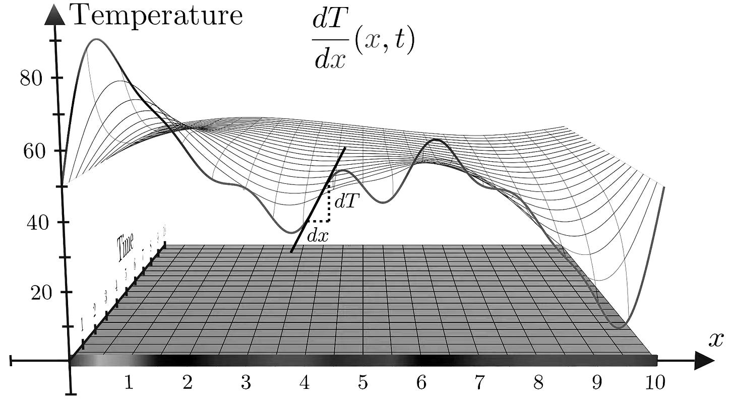
Now, let’s add an additional component/dimension and attempt to model how the temperature in our metal slice is dispersed with time. What happens when we map the above function to our new system?
Indeed, looking at the above, we can see that we obtain a function which ‘evolves’ in time! As we move across our time dimension, our function ‘smooths’ out so that our temperature is distributed evenly across our x-space. This is what the heat equation describes! In simple terms, our graph above shows how the heat flows and how the temperature changes with time!
We also note that the nature of our new field equation makes things more difficult to model than what we saw in our earlier temperature example. The reason for this is due to the fact that we’re not only using the positional coordinates to model the field, but also a time coordinate as well! This is what makes our differential equation above a partial differential equation rather than an ordinary one!
That is, in addition to taking the differential of our temperature in regards to our positional (x) component, represented as dT/dx and shown below:
we’re also modeling how our temperature evolves with time (represented as dT/dt):
Because each one of our 2 above derivatives only tells us a partial story of how our function (or field) changes, we call them partial derivatives and we thus end up with a partial differential equation for our scalar temperature field!
Note also: we simplified our example to ignore the temperature field values present in our y dimension! Here, we’re showing a simplification of what would happen if we isolated our system and metal strip from the rest of our sheet. We did this so that we could get a good visual intuition of how to model a very simple field. If we wanted to get a more accurate real world picture, we would need to model the real heat equation which describes our scalar field evolution in terms 4-dimensional space defined as T (x, y, z, t)! In regards to our 2-dimensional metal sheet example, we would only need to define it in terms of T (x, y, t) – but you get the point! We simplified our case to show the principle in action. A real field equation may not be so simple!
Vector Fields
Not all fields are scalar. Let’s assume that we decide that we want to model a velocity field created by a fluid. We can’t model the motion of a fluid using single numerical values. Instead of outputting a scalar, we create a function which outputs a vector with a direction and magnitude!
That is, for each point coordinate point in 3-space (x, y, z), our function outputs the direction and magnitude of the fluid displacement at that point, and we thus get a simple vector field modeling the fluid flow:
A vector field doesn’t have to represent fluid flow though! We can use vector fields to model the force of gravity as well:
Below is another example showing a vector field for something which lies of central importance to us: the magnetic field!
We can obtain a lot of information about a vector field by looking at how the arrows are distributed over the plane. Going back to our fluid example: we can imagine that the 2-dimensional plane we’re looking at is covered in fluid, and that each arrow tells a particle passing through it what its velocity is.
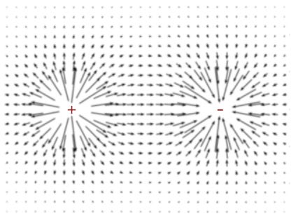
As another note: this fluid doesn’t have regular flow like an everyday fluid may have. It may have ‘sources’ or ‘sinks’ where more fluid flows out than what flows in, and vice versa. Using the example of electric charges, we can imagine our electric charge ‘points’ as being sources or sinks of an electromagnetic fluid, and the arrows representing how this field flows between them:
To get an accurate conception of the source and sink idea though, we need to get familiar with the concept of divergence, which we illustrate in the next section.
Divergence
Specifying the divergence of the vector field at a point is equivalent to telling how much "denser" the fluid is getting near it. So, if we know that the arrows seem to be directed toward this point, the fluid particles tend to aggregate around it, and we say that the fluid converges there, or that it has negative divergence. Instead, if the arrows seem to be pointing away from the point, then the fluid is "thinning out", the fluid particles tend to escape from it and we say that the fluid diverges from there and has positive divergence. If the fluid seems to do neither, then we say that the divergence there is approximately zero or zero.
We can phrase this in simpler terms: let’s draw a small circle centered at the point whose divergence we want to measure. If there are more arrows going out of the circle, then we have a source point and a positive divergence. If there are more arrows pointing inwards and into the circle, then we have a sink point and a negative divergence.
In the below example, we can see one point which acts like a 'source' (fluid flows out) and thus we can see that it has a positive divergence:
On the flip side, if in a small region around a point there seems to be more fluid flowing into it than out of it, the divergence at that point would be a negative number:
Let’s show a more precise example, just so that we can make sure that there’s no confusion about what the divergence represents.
Remember that in 2 dimensions, the vector field is a function that takes in two-dimensional inputs and spits out two-dimensional outputs. In the example below, we can see a 2-dimensional field example which takes 2 coordinates and transforms them into a vector:
In the case above, we can see that the input coordinates where x = -3.75 and y = +1.23 return a vector at the point which generates a vector which points -0.58 units in the x direction and -1.00 unites in the y direction.
The divergence of that vector field is a new function. This function takes only a single 2-dimensional point as its input, but its output depends on the behavior of the vector functions/fields in a small neighborhood around that point. As we already stated in our previous example, if the sum of the vectors going out at or around that point are larger than the vectors going in, we state that the divergence is positive. In the example below, we can see that the vectors at point x = 4.25 and y = 1.25 are ‘flowing out’ of our point, so we quantify the divergence as being positive (+0.65):
You can think of the divergence as being similar to a derivative function. The output of the function is just a single number which measures how much that point acts as a source or a sink. If it is a source, then we have a point with a positive divergence. If it’s a sink, the divergence is negative.
Curl
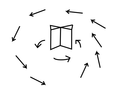
You can think of the curl of a vector field being similar to the divergence, except that instead of measuring whether the point is a source or a sink, the curl tells us how much the fluid is ‘rotating’ around it. To be exact: the curl measures the rotation of the field in the counterclockwise direction.
If you draw a small circle centered at a point, and the arrows around the circle are telling the ‘fluid’ or field to rotate in a counterclockwise direction, then the vector field has a positive curl. On the other hand, if the arrows point in a clockwise direction, then the curl is negative. If the fluid or field has no rotation along our circle or point, we have a curl which is either zero or close to zero.
As a note: a point in a region where the vectors are going in one direction could have a non-zero curl, as illustrated below:
In the example above, we can see that the field shown will generate a larger force near the top of our circle than near the bottom. If we were to place an imaginary paddle wheel near it, the force generated would cause it to spin in the clockwise direction, so in the above instance, we say that the region has a negative curl.
Although it may seem that the curl function is scalar, the reality is that in 3-dimensional space, when we take the curl, we get an output vector which characterizes the rotation around that point according to a certain right hand rule. As we mentioned previously, a great analogy which we can use comes in terms of an imaginary paddle wheel. Imagine if we were to place this wheel at the point at which we want to measure the curl. If our field around this point causes the paddle wheel to turn in a clockwise or counterclockwise direction, then we obviously get our curl term: the faster the paddle wheel twists or moves at the point, then the stronger the magnitude of the curl.
In the above example, we can see a demonstration of an imaginary paddle wheel at a point which has a positive curl and is surrounded by a field which pushes our wheel in a counterclockwise direction.
Now, if we were to extend this from 2-dimensions into 3, our curl function would simply output a vector which would show us in which direction to place our wheel such that we can maximize the work done by our field. We won’t go into too many details in illustrating the 3-dimensional concept though. For now, we’re going to focus on our simplified 2-dimensional case, which associates numbers and scalars rather than vectors. This is sufficient for what we need in order to finally get a clear conception on what we came here to understand: the meaning of Maxwell’s equations!
Maxwell’s Equations
As we already discussed, vector fields that represent fluid flow that have an immediate physical interpretation: the vector at every point in space represents a direction of motion of a fluid element, and we can construct snapshots of the motion of this fluid by drawing vector images over certain regions of space, just like we did in the previous section.
Now, for a more general vector field, such as the electromagnetic field discussed below, we do not have that immediate physical interpretation of a flow field. There is no “flow” or fluid that’s really present along the direction of those fields! However, even though the vectors in electromagnetism do not represent fluid flow, we carry over many of the terms we use to describe fluid flow. For example, we will speak of the flux of the electric field through a surface. If we were talking about fluid flow, “flux” would have a well-defined physical meaning, in that the flux would be the amount of fluid flowing across a given surface per unit time.
Noting this, let’s finally dive into the equations and try to interpret exactly what they mean. Below, we present the equations in differential form – that is, we present them in terms of the curl and the divergence of the vector field:
After showing them in this form, we’ll then go on and present the same exact equations in integral form. The main difference between the two is in the perspective: the differential form focuses on presenting the electromagnetic field in terms of the curl and divergence of individual point charges, while the integral form focuses on presenting it in terms of a surface integral.
As already mentioned, the equations on the left are phrased in terms of the curl and divergence. The equations on the right are equivalent to the ones on the left, except that they phrase divergence and curl in terms of the dot and cross product, and we use arrows in our equations to denote that the fields we’re working with are vector fields rather than scalar fields.
Finally, let’s dive into what the 4 equations mean / represent!
Gauss’s Law for Electric Fields
The top equation is Gauss’s law for electric fields. It states that the divergence of an electric field at a given point is proportional to the charge density at that point:
Unpacking the intuition for this in terms of divergence, you can imagine positive charges as being sources of some imagined fluid, and negative charges as the sinks of that fluid:
Another example:
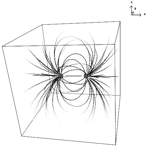
We can also model the above picture in terms of flux, which is similar to the earlier concept of using vector fields to model our fluid flow. The idea is exactly the same, except that instead of using vectors and vector magnitudes spread through every point in space, we use flux lines flowing from a source to a destination.
Let’s show an example by drawing flux lines and showing how they relate to our earlier examples. Faraday called these field lines “lines of force” and believed that they had an existence of their own, describing them as stretching across a vacuum.
To draw a flux line, start out at any point in space and move your pen/pencil a very short distance in the direction of the local vector field. After that short distance, stop and find the new direction of the local vector field at that point. Now, begin moving again in that new direction (the direction of the arrow at the point that is). Continue this process indefinitely. By following this methodology, you can construct a line in space that is tangent to the local vector field. If we do this for different starting points, we can draw a set of field lines that give a great representation of the properties of the vector field, as illustrated below:
So how do we use the flux lines to determine the strength of the field? When we used vectors, we could show the strength by going to a point and using the magnitude of our vector. In regards to flux lines, we no longer have this capability. To determine the strength of our field using flux lines, we simply use the density of field lines at some region of space. The total number of lines crossing the area / volume indicate the strength of the field at that region. This means that there is a direct proportionality between the electric field and the flux lines.
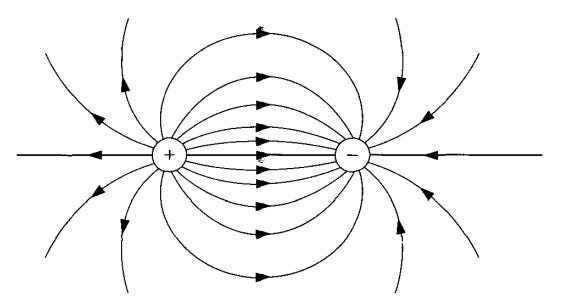
Once again, we can imagine that our flux lines have a direction. We draw the direction of our lines away from positive charges and towards the negative charges:
We can demo the concept of flux between 2 opposite charges using the diagram below:
A diagram showing the flux lines flowing between 2 like charges:
As you can see from the figures above, the field line densities increase near our charges and drop off moving away from them. This shows that the electric field from a point charge decreases with the distance from it. We can thus see that the electric field strength, which is also sometimes referred to as the electric flux density, obeys the inverse square law:
The inverse square law not only applies to electric fields, but many different phenomena, such as gravity and sound as well. The law can easily be pictured through geometric intuition of visualizing an expanding sphere. As it expands, the force can be viewed as being distributed throughout the surface area. In other words, the force spreads out in an ever expanding spherical shell as the sphere moves radially and the surface area expands by r2 (a spherical surface area is equal to 4πr2):
We can see that as we expand our spherical shell outwards, we get a decreasing concentration of the electromagnetic field as the flux density is spread out across our circular surface. Let’s take an arbitrary area located at an arbitrary distance d from our center. We can see that when our radius r = 3d, the area which our flux lines pass through is 9 times larger than the area that it passes through when r = d. When r = 4d, our flux density expands into an area which is 16 times larger (r2 = 42 = 16), so our field strength is reduced by a factor of 16! We should be able to easily see what the field strength diminishes by a factor of 1 / r2 (inverse square) as we travel away from an arbitrary point of charge.
Why are we spending this much time discussing Gauss’s law in terms of flux? We already have a good intuition of what it states when it comes to divergence: electric fields produced by electric charges diverge from those positive charges and converge to the negative charges. The reason we want to get a good intuition behind flux is so we can present this concept in terms of its integral form, which relates the same concept we just discussed in terms of integrating the surface area around a charge rather than expressing it through divergence!
What is an integral, and what do we mean by integration?
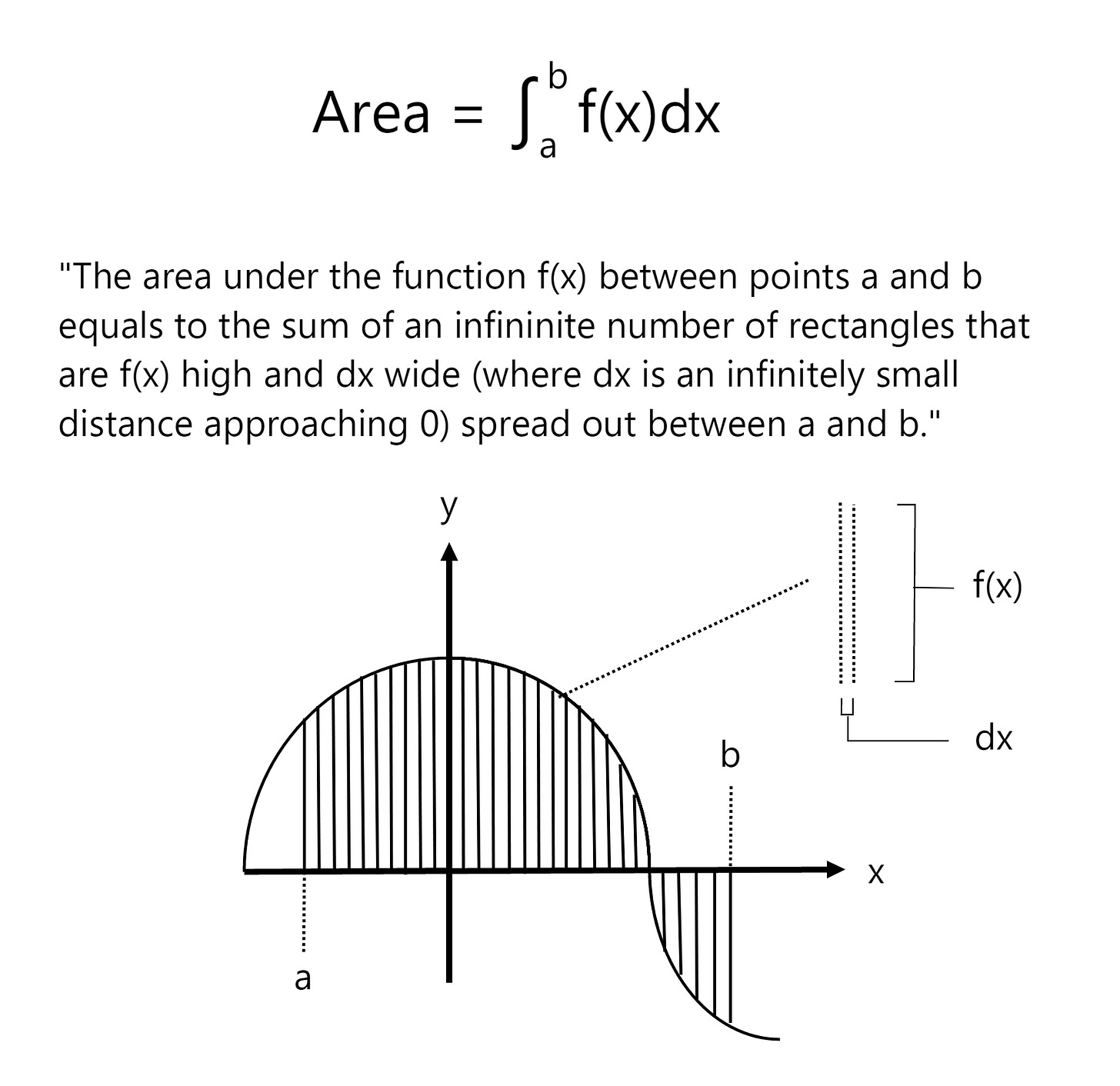
The motivation behind integration is to find the area under a curve. To do this, we break up a function interval (whose area we want to measure) into little regions of width Δx and add up the areas of the resulting rectangles.
Here's an illustration showing what happens as we make the width (Δx) of the rectangles smaller and smaller:
Indeed, as Δx approaches 0, we obtain even more accurate values representing the area under the curve! When we take an integral of something, that’s all we’re doing! We can think of the integral as being a direct translation shown below:
Using the above methodology and finding the integral function (which we call the anti-derivative), we can find the area between point a and b!
This concept plays a central role in calculus, and a central role in modeling our integral equations, so let’s now express Gauss’s law in terms of our integral formulation:
In integral form, Gauss’s law states that an electric charge produces an electric field, and that the flux / charge surrounding the field and passing through any closed surface is equal to the total charge contained within the surface. The total charge always equals to the number of point charge (or charges) which the surface envelops. We also notice the inverse square law in action once again: since our surface integral is always going to equal to the enclosed charge, as we travel away from our enveloping spherical shell, our charge / flux density will get weaker by a factor of 1 / r2. We can see that in the spherical example in the image above that the total charge passing through the surface area is going to equal to qenc / the electric permittivity of free space (ε0), which is equivalent to what we have in our equation in differential form.
But what is the electric permittivity of free space (ε0) though? We haven’t had a chance to discuss this term yet! To put things simply: the electric permittivity is a constant which allows us to describe how easily (or how difficult) it is for electric fields to pass through a medium (such as air, or water, or anything else for that matter). It’s called permittivity because of how much a given substance “permits” electric field lines to pass through them. So for certain substances, our electric field lines will pass through them easily, and for other ones, they won’t. This term encapsulates this permittivity. But what does this value for free space represent? The permittivity of free space has a special value and represents a the ability of a vacuum to let electric field lines to pass through. Its value is normally expressed as 1A2s4kg−1b−3.
Once again, we can say that our integral form is the same exact equivalent to our differential form. Whereas our differential form expresses the concept of having a charge modeled in terms of fluid flow and convergence and divergence (and that an electric field produces a charge which diverges from positive charges and converges towards negative charges), our integral form expresses the same idea, but in terms of capturing the field flow over an enclosed surface using integration. Here, we integrate the total surface area of a closed surface by summing small surface area elements (da) and adding them together to get the total charge / flux over that area, and we note that the total electric field encapsulated by this surface area will always equal to the total charges enclosed within that area.
And, that’s it! We’re now equipped and ready to tackle Gauss’s law for magnetic fields!
Gauss’s Law for Magnetic Fields
Gauss’s law for magnetic fields is very simple, and simply states that the divergence of a magnetic field is always 0:
If we once again go back to attempting to model this through fluid flow, we can say that the statement above indicates that the magnetic fluid is in-compressible, with no sources or sinks anywhere:
In terms of modeling this through flux, we could state that the flux of the magnetic field through any enclosed surface area will always be zero! This is often interpreted as “there are no magnetic analogues to charges” (called magnetic monopoles). You may then ask: so how do we get magnetic fields? How do we get permanent magnets for example, and what is their ‘source’ if these fields never really have a ‘net’ divergence?
Well, in order to produce the magnetic field, we don’t need sources or sinks! We can produce one through variation, or the concept we touched upon earlier: the curl. We can model our magnetic field functions in space such that when we sum all of our enclosed surface areas, we always get 0, but the net curl or ‘rotation’ generated by the field results in an asymmetry in the distribution of the vectors and thus as having ‘circulating’ field lines of force which are capable of doing work. This ‘circular’ field throughout space is what produces magnets and the magnetic field, and we think of the magnetic field as being a by-product of a moving electric field or moving electric charges.
We can once again go back to our original question then and ask: so what are magnets? For the most part, in most materials, the electron ‘spins’ (a term we use to describe a set of properties, one of them being its magnetic field orientation) are oriented relatively evenly / randomly, which results in a net magnetic charge which is close to 0. On the other hand, in magnets, the electrons are oriented in such a way that a large majority are aligned in one ‘direction.’ Because of this asymmetry and alignment in the orientation, or as we mentioned earlier, the atomic spins within our material, we get a resulting net magnetic field and the equivalent of a circuit. This circuit in turn produces our magnetic field and results in a magnet!!
Let’s try to visualize the magnetic field, which is drawn and demoed below:
Gauss’s law for magnetic fields essentially states that the magnetic field has a divergence of 0, and that the total resultant ‘magnetic charge’ of any magnetic field will always equal to 0. In terms of flux, what this means is that unlike electric flux lines, magnetic flux lines do not originate and terminate on charges!! Instead, they always circulate back on themselves and form continuous loops.
We can once again express this using an integral form, which simply states the same thing as our differential form in terms of enclosed surface areas:
The above equation tells us that when we take the total net magnetic flux over a closed surface area, we’ll always get 0. We can think of magnetic flux going through a surface as always being a two-way street: any outward flux going out of the surface will always be balanced by an inward flux going into it! The equal amounts of outward (positive) flux and inward (negative) flux will always cancel, and we’ll always end up with a net amount of magnetic flux which equals zero.
As a note, although we always use the example of having an enclosed spherical surface, the above principle applies to any closed surface which we may place within a field! It could be a cube, sphere, torus: any surface which magnetic flux lines penetrate will always be balanced and will always equate to zero!! The same principle and concept applies to electric fields, except that whichever enclosed surface we choose to use, we’ll always get a net electric flux which equates to the net amount of charge present within the surface!
Noting the above, we’re now ready to show the meaning of our last 2 equations, which describe the complementary nature of our two fields! The equations tell us that a time-varying magnetic field produces a spatially varying electric field, and vice versa.
Faraday’s Law
Faraday’s law tells us that a changing magnetic field induces an electric field:
The above equation reads: "A circulating electric field is produced by a magnetic field
that changes with time. The direction of the circulating electric field which is generated opposes the magnetic flux.”
In terms of curl, this means that as the magnetic flux increases, it generates a circulating electric field in the clockwise direction. If it decreases, the generated electric field is in the counterclockwise direction.
We can get a good intuition of this by looking at our diagrams below:
In essence, the above behavior encapsulates the basic relationship we already outlined. The more quickly the magnetic field increases in a certain direction, the more strongly the electric field will curl against it (the “against” bit of this statement also has its own name, and is called Lenz’s law).
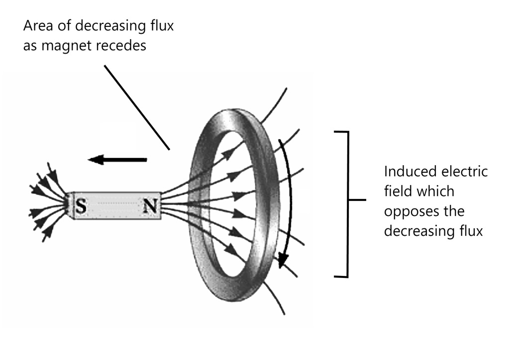
Another diagram which illustrates how our changing field opposes the change in flux is shown below:
In the above illustration, the circulating electric field which is induced and flows within the ring circulates in a direction such that the magnetic field it produces (represented by the dashed lines) opposes the increase in flux through the ring. We thus have a counter-balancing electric field which is generated any time we have a change in magnetic flux!
We must note once again that although the electric field induced through Faraday’s law has the same properties as our regular electric field, the resulting structure of this circulating field definitely differs from what we’re usually used to seeing when it comes to electric fields! We noted earlier that we could always think of the electric fields as originating from a source points (which we call positive charges) and as terminating at sink points (which we call negative charges). These charge-based fields always seem to have a source and sink (and thus, a non-zero divergence at those points)! In other words, in these instances, we could think of point charges as being the originators of the electric field. Now, with our new law, it seems that we have an induced field which doesn’t have an origin!
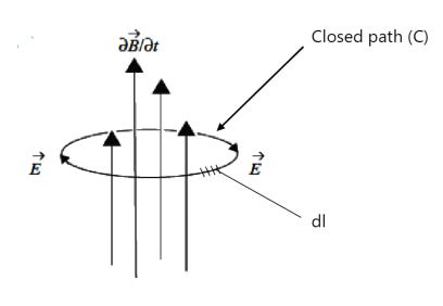
With Faraday’s law, we have induced electric fields which have field lines that loop back on themselves, with no points of origination or termination. Our induced field therefore has a divergence of zero! So, once again, we note that the resulting electric field is simply a circulating field which loops in around itself (thus, resulting in a net curl which opposes a magnetic field)! We can picture a simple 2-dimensional circulating electric field using the diagram below:
We note that since these changing magnetic fields are capable of inducing electric fields with closed loops, they’re also capable of driving charged particles around continuous circuits. We already demonstrated this in our diagrams, when we tried to show how the induced fields opposed the changing flux, but this also means that we can use Faraday’s law to create currents / generators and convert mechanical energy into electrical energy, so this law plays a central importance in our everyday lives! It’s what makes generators and conversion of mechanical energy into electrical energy possible!
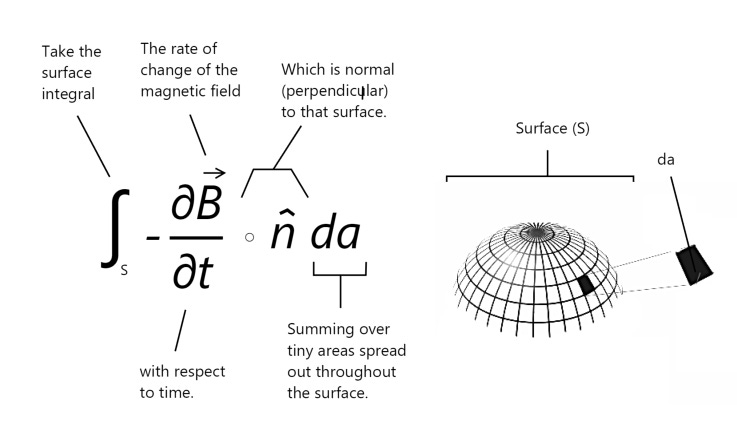
Let’s present Faraday’s law in its integral form. Although it may look a lot more complex than our differential formulation, it essentially states the same thing!
The left hand side of our equation represents the line integral of an enclosed electric field, which we also call the circulation of the field.
What exactly does the circulation represent? Well, since our induced electric field is capable of generating a current by moving a charge (or charges) around a loop, we can think of the circulation as representing the work done by the electric field in moving a unit charge around the closed path (C). We also call this the electromotive force. We can note that this term is is adjacent to what we term as the curl of the generated electric field in our differential form of Faraday’s law.
The right hand side of the equation represents the rate of change of magnetic flux. Here, we simply take a sum total of tiny surface area segments denoted by da:
We thus have the integral form for what we deemed as the total change in flux over the area, and the negative sign in our equation simply denotes the fact that our circulating electric field opposes the flux.
Our above equation thus has the same meaning as the equation in its differential form: a changing magnetic field / flux induces a circulating electric field which opposes the flux!
We thus end our presentation of Faraday’s law and move onto the last equation, which is the Ampere-Maxwell law!
Ampere-Maxwell Law
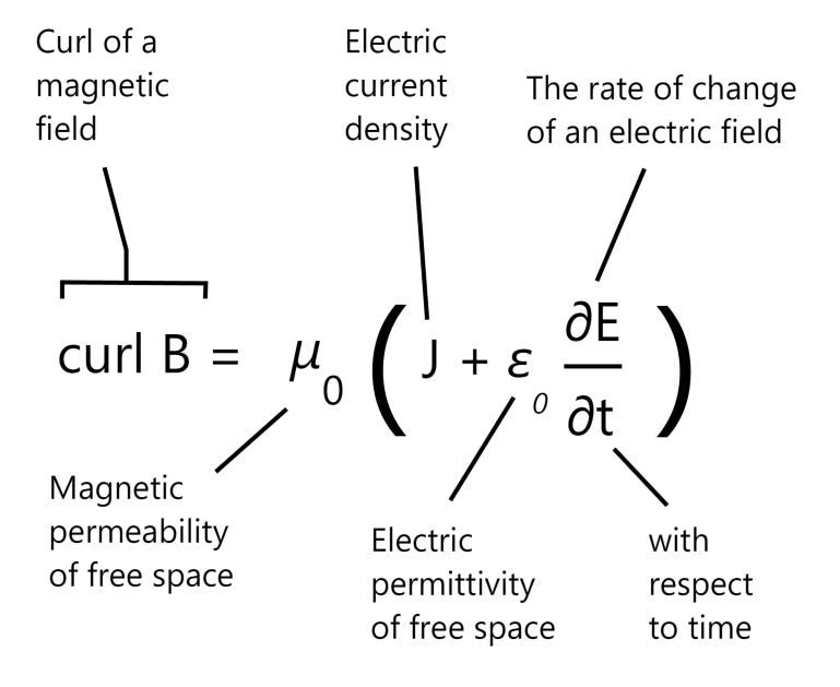
In a similar manner as to our first curl relation which expressed Faraday’s Law and stated that a changing magnetic field produced a circulating electric field, the last equation tells us that an electric current or a changing electric field (or both) induce a magnetic field!
The left side of this equation is a mathematical description of the curl of the magnetic field while the two terms on the right side represent the electric current density and the time rate of change of the electric field. The equation essentially states that “An electric current or a changing electric field induce a circulating magnetic field.”
What does this mean exactly? And how can we picture the induced magnetic field?
We can capture this through a simple visual shown below, which show a circulating magnetic field produced by a moving electric current I:
The left hand sign of our equation simply expresses the curl of the magnetic field. The magnetic field, unlike the electric field, doesn’t have any ‘sources’ or ‘sinks,’ and there are no magnetic charges which can be used to produce them. All magnetic fields are therefore circulating fields: they always loop back upon themselves. We’ve already encountered circulating loops in our Faraday’s equation, which expressed a similar concept in relation to induced electric fields and which used a curl function to express this relationship. Here, we simply use the curl as an expression for the circulating magnetic field, and the equation states that this field is induced through one of two conditions:
1. An electric current: this is the first term expressed to the right of our equation, which we denoted as J and which denotes the electric current density.
Prior to defining density though, we need to establish what an electric current is: an electric current is simply the rate of flow of electrical charge across some defined cross-sectional area. The “rate of flow” of charge represents the charge over time (charge/time). This calculation gives you the number of coulombs that go past a point in a second within an electrical circuit.
A lot of people like to associate currents with a flow of electrons present within a wire, but we must note that this view isn’t as simple as it seems: a current isn’t just a movement of charged particles, like electrons in a wire! "Electric charge" is not a "thing". It is a property of other things, like electrons and protons. In fact, we don’t need moving charges to produce an electrical current! We could have things which act like electric currents with no physical movement involved! We don’t have time to discuss the full extent of this. For now, we simply note that a current doesn’t necessarily equate to moving electrons!
Now, imagine that we have a current flowing into the page. The induced and circulating magnetic field produced by such a current is visualized below:
We can see that in the above diagram, our induced magnetic field curls in the direction of our current, and we can use the right-hand rule to get a clear conception of this. Imagine that the electric current is flowing out of the page, and place your hand on top of the paper / page. If you point your thumb upwards, you can now get a clear picture of the direction of the induced circulating magnetic field, which is shown below:
Let’s also try to visualize the precise mathematical meaning behind the electric current density (J). The current density is defined as the current flowing through a unit cross-sectional area perpendicular to the direction of the current. In other words: it measures the amount of charge passing through the imaginary surface:
We thus have our first condition for inducing a magnetic field: an electric current / current density!
2. Changing electric field with respect to time: this is the second component (∂E/∂t) within the Ampere-Maxwell equation.
One question which you may ask is: well, if a changing electric field produces a circulating magnetic field, why do we need to separate terms to express this relationship? Couldn’t we tie our first component in with our second component and express the Ampere-Maxwell equation in terms of the electric currents only?
The answer to that questions is no. We don’t need a flowing current to produce a magnetic field! A changing electric field produces a changing magnetic field, even when no charges are present and where we might not have any physical current flow! The second expression in our equation expresses this fact!
Finally, let’s re-iterate our 2 conditions once again to summarize the equation: an electric current or a changing electric field are capable of generating a circulating magnetic field!
Let’s show one more visual illustrating this concept. To do so, we use a solenoid, which is a coil of wire wrapped in a cylindrical manner and which can be used to generate a magnetic field:
Because our wire is wrapped in such a manner, the resulting magnetic field generates a flux which passes through our coils and circulates around our solenoid, resulting in a magnet!
We now express the Ampere-Maxwell law in integral notation:
We can once again state that the equation in integral form has the same exact meaning as the equation in differential form. Essentially, we replace the curl with a line integral of an enclosed magnetic path, and instead of using the electric current density and the rate of change in the electric field with respect to time, we now use the enclosed electric current and the rate of change of electric flux!
We should already know what the first term in the equation relates to: we simply take line integral of the enclosed magnetic field to encapsulate its circulation / curl:
We should also take note that the above relation implies that the inverse square law for magnetic fields! That is, if we were to take a current going through a wire and measure the magnetic field which it produced, we would notice that the strength of the magnetic field which circles around the wire gets weaker by a factor of around 1 / distance2 as we move further from the current!
Let’s move on to the right side of the equation. The diagram below shows what the first term (Ienc) relates to:
We can see that in our above example, we have an enclosed current with a net flow going through our surface. To be exact: we have a current I which penetrates the surface (S) at only one point, so in this instance, we have an enclosed current of +I.
What would happen if we were to create a loop such that the current flowed backwards through our enclosed surface?
In the instance above, our current penetrates the surface in both directions. In this instance, the net current penetrating the enclosed surface is 0!
We conclude that the Ienc enclosed term relates to the net current penetrating our enclosed surface. What really counts here is the net penetration, and not simply the total current which flows past the enclosure!
Noting this, we can move on and decipher the second term:
In the above equation, we simply express the change of electric flux through a surface C. This relation was already explained when we discussed our equations in integral form, so we won’t spend much time explaining it here. Essentially, it represents the rate of change of electric flux.
We note that the electric permittivity and magnetic permeability terms both relate to the resistance of the medium to electric and magnetic fields. When it comes to permittivity / permeability of free space, we note that the 2 constants are related to one another, and equal ε0μ0 = 1/c2, where c represents the speed of light. Really, they’re dimensional constants which go away if we change our equations so that they’re expressed in Gaussian units. In other words, they’re essentially dimensional values that don’t have any physical significance!
Congratulations, you’ve survived through both the integral and differential forms of all four of Maxwell’s equations! Are we finally finished?
Not quite yet! We have one last section which we want to go through. This section deals with bringing a unified picture which combines our two fields into one!
Unification: The Electromagnetic Field
The magnetic and electric fields are really one unified concept which we call the electromagnetic field.
A better and easier way of visualizing the relationship between the two fields is provided below, where we show the vectors describing an electromagnetic wave (light) in 3 dimensions:
Here, we can see how the electric field vectors, the magnetic field vectors, and the direction of propagation are all aligned. We note that the electric field and magnetic field vectors are mutually perpendicular! We won’t worry too much about the Poynting vector, which relates to the propagation of the electromagnetic field - we mostly want to emphasize the fact that the electric and magnetic fields are always aligned in such a manner so that a change in one compliments the other!
Although the four equations may give us the notion that we have two separate fields which we must account for and which we call the electric and magnetic fields, here, we finally reveal a surprise: there’s only one field, and we call it the electromagnetic field!
So what happens to our 2 separate fields then? How is this possible? Well, we can actually model the magnetic field as being a product of relativity and relativistic effects produced from a changing electric field!
That’s right: with the proper choice of frames, a magnetic field can always be explained as a type of electrostatic attraction or repulsion made by relativistic effects of the electric field!
Let’s suppose that we have a current flowing through a wire. We place an electron next to the wire, and pretend that it’s moving in the same direction and velocity as the electrons within our wire. Using the right hand rule, we can find the direction of the wire’s magnetic field. That is, the rule will show us that the wire will attract our moving electron.
Let’s say that we were standing still and observing this. We could say that from our reference frame, this result was produced by the induced magnetic force! The wire, from our perspective, doesn’t have a charge density flowing through it! It should be neutral, as the net amount of positive and negative charges look equal!
What if we were to decide to move next to the electron though, such that we were moving in the same direction and with the same velocity? Indeed, now we would be experiencing the world through a different reference frame! From this reference frame, our charge isn’t moving at all, and thus, there is no magnetic force! Only moving charges / fields produce a magnetic force after all. So, what happens now?
Well, in special relativity, when objects move uniformly, they undergo a contraction in length along the direction of motion. We call this the Lorenz contraction. This essentially means that the moving objects appear shorter to observers at rest. A simple example of relativistic length contraction using a baseball is provided below:
The image above shows what happens to the length of a baseball as it moves closer and closer to the speed of light: its length keeps contracting the faster we go!
Now, let’s get back to our original example and pretend that we’re moving along the same path as our electron. Once again, from this reference frame, the electron is standing still and the flowing electrons within our wire are also standing still as well! Here, the positive metal ions appear to be moving, and they’re moving backwards to our reference frame!
Now, let’s think about this: what happens when we have moving objects? Once again, we must remember that the faster we move, the more our length gets contracted. In the instance above, our positive ions will get ‘squished’ along their direction of movement. What happens if you squash charged objects such that they occupy less space along their lengths? That’s right, the positive charges along the length of our wire will be compressed, resulting in a higher density of positive charges per centimeter of wire!
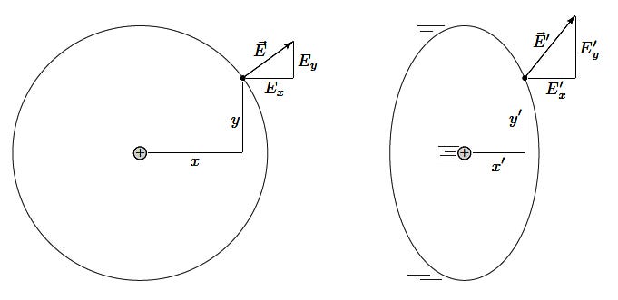
The diagram below does a better job of showing the exact effects of length contraction on a charged particle, as well as its effect on the particle’s electric field:
In the diagram on the left, we see a point charge which is symmetric along its length and thus at rest. We can picture the electromagnetic field as pointing directly away from the charge, with no effects of contractions taking place on our charge. On the other hand, if we take a look on the right, we imagine a moving particle. Here, our reference frame shows the particle moving to the right. The effect of this movement shows that its length is contracted in the direction of movement. The effect that this has on our moving field is such that the vertical component is stronger! Taking a look at our arrow (representing the electric field), we can easily see that this effect combines to make the field lines / arrows point directly away from the current location of our charge!
Let’s show another image which shows the relativistic transformation of our field as it moves to the right of our page:
Once again, we should be able to see that the vertical component of our field is compressed and thus stronger due to length contraction!
Let’s once again go back to our original example. From the electron’s reference frame, we can see that although we have no length contraction in terms of our negative charges, we do have length contraction in terms of our positive charges which are flowing to the left of our reference frame. Since this has an effect of compressing the length of our positive ions, the electrons within the wire can no longer fully cancel out the positive ion fields, leaving the wire with a net positive charge! This results in a net attractive force on our charged particle which is directed towards the wire:
We can see in the above instance, from the electron’s reference frame, we no longer need a magnetic field to explain the force exerted on our charged particle! We can describe the resulting magnetic force as a product of relativistic length contraction of the electric field!
This is a simple example that shows that the electromagnetic field really is a single field whose overt manifestations can change dramatically depending on the frame from which they are viewed.
In fact, in Part VI of his 1864 paper titled ‘Electromagnetic Theory of Light,’ Maxwell combined displacement current with some of the other equations of electromagnetism which resulted in a wave equation with a speed equal to the speed of light. He commented:
“The agreement of the results seems to show that light and magnetism are affections of the same substance, and that light is an electromagnetic disturbance propagated through the field according to electromagnetic laws.”
In a vacuum and charge-free space, we can actually express Maxwell’s equations with the equations shown below:
We can use the vector identity:
and apply it to the third and fourth equations to get:
That shows that the electric and magnetic fields satisfy the wave equation! That is, electromagnetic waves exist! Furthermore, since 1 / μ0ϵ0 = c2, we know that they travel at the speed of light!
Side Note: if you need a more in depth explanation on how to derive the above, this link does a good job of explaining how to derive the above equations, and you can watch this video to get a better intuition behind the equation itself.
Prior to ending our presentation of Maxwell’s equations, let’s quickly glance at another overview (with some additional details added in) to show how divine and powerful Maxwell’s equations really are:
What’s so special about the above table? In Feynman’s own words:
In Table 18–1 we have all that was known of fundamental classical physics, that is, the physics that was known by 1905. Here it all is, in one table. With these equations we can understand the complete realm of classical physics.
First we have the Maxwell equations—written in both the expanded form and the short mathematical form. Then there is the conservation of charge, which is even written in parentheses, because the moment we have the complete Maxwell equations, we can deduce from them the conservation of charge. So the table is even a little redundant. Next, we have written the force law, because having all the electric and magnetic fields doesn’t tell us anything until we know what they do to charges. Knowing E and B, however, we can find the force on an object with the charge q moving with velocity v. Finally, having the force doesn’t tell us anything until we know what happens when a force pushes on something; we need the law of motion, which is that the force is equal to the rate of change of the momentum. (Remember? We had that in Volume I.) We even include relativity effects by writing the momentum as:
If we really want to be complete, we should add one more law—Newton’s law of gravitation—so we put that at the end.
Therefore in one small table we have all the fundamental laws of classical physics—even with room to write them out in words and with some redundancy. This is a great moment. We have climbed a great peak. We are on the top of K2—we are nearly ready for Mount Everest, which is quantum mechanics. We have climbed the peak of a “Great Divide,” and now we can go down the other side.”
Indeed, in a few simple lines and equations, we’ve summarized the classical world.
Resources / Credits
The main inspiration for this guide was a video by 3Blue1Brown / Grant Sanderson titled ‘Divergence and Curl: The language of Maxwell's equations, fluid flow, and more’ which can be found here:
The images illustrating vector fields, as well as the concepts included in the curl and divergence sections were taken directly from the video.
The images shown when explaining the heat equation and partial differential equations were also taken from the video series by 3Blue1Brown / Grant Sanderson called ‘Solving the Heat Equation’ which can be found using the link below:
In addition to the above resources, the guide also references A Student’s Guide to Maxwell’s Equations by Dan Fleisch which provides an excellent guide to understanding the exact meaning behind all of the equations (in both integral and differential form).
Other notable references and illustrations can be found using the resources listed below:
You can also find the original write-up of this post directly in my GitHub repository:
Thank you for reading, and if you like these types of visual expositions, please like and subscribe.


